2D drawing of front elevation.
Traditional method of architectural design presentation.
Design Tools |
|
Synoptic Designs uses state of the art 3D modeling CAD (Computer Aided Design)
software for design tasks. Use of 3D modeling allows both the designer and
the client to fully comprehend the appearance and spatial relationships
of architectural designs in their entirety prior to construction.
See
the complete list of available hardware and software at the bottom of this
page.
It is also possible for clients to install free viewing software on their home computer and to view (rotate, pan, zoom, turn model components on or off) models developed during the design process in virtual 3D space at their leisure. Text and images below are provided to explain the differences between traditional architectural design tools and the modern computer based tools we employ. |
|
Click on thumbnails below to open a larger image in a new window. |
|
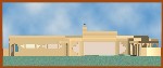
2D DRAWINGS - The old way. Can you tell what it will really look like? This is the type of output you would expect from the typical design/build contractor or architectural draftsman preparing plans for your residence. Of course you would also be provided with the other orthogonal views (side & rear elevations, plan and interior floor plan)and then be expected to integrate the views in your minds eye to determine the actual 3D form and appearance of the structure. |
|
|
2D drawing of front elevation. |
Traditional method of architectural design presentation. |
| ARTISTIC
RENDERINGS - A step up in comprehensibility, but not in common use in the
area. Architects (as are most academically trained designers in general)
learn in school to create hand drawn renderings for presentation, at the
expense of hours of labor, but a contractor or architectural draftsman would
have to subcontract to an artist or illustrator to spend the time to create
a color rendering based on the 2D drawings. Normally you would be provided
with a single rendering, either of the elevation or (at extra expense) with
a single perspective view. If there are any design changes a client would
either have to pay for another rendering created from scratch or forgo seeing
the effect of the changes.
|
 |
2D Rendering of front elevation. |
Hand drawn rendering may be provided at extra cost by some designers/contractors. |
|
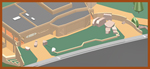
3D MODELING - A virtual model of the project is created in the computer with CAD software. Although the images below are 2D on your screen they are derived from any arbitrary view of the 3D model. In the front and rear views below the images have been enhanced by using photo realistic imaging software that accurately represents the position of shadows based on the position of a simulated sun light source, in the front view approximately as would be the case on a late summer afternoon; early winter morning in the rear view. |
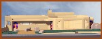 |
Front View - shaded rendering derived from 3D model. |
Shaded view from any angle quickly generated from 3d model. |
|
It is also possible to locate a simulated sun in relation to the model exactly as the sun would relate to the actual structure at any time of year and at any time of day and to view the resulting shadows on the exterior and in the interior through the windows and doors. This capability allows a determination of how sun and shadow interact with the structure, a vital aesthetic consideration in architecture, and is an invaluable tool for designs utilizing passive solar architectural principles. |
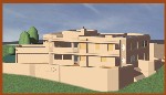 |
Rear View - shaded rendering derived from 3D model. |
Possible to accurately represent sun shadows for any time of day or year. |
|
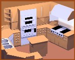
But wait! There's more. The model is not just of the exterior. The model is also detailed in the interior. Remove the virtual roof from the model and you have the view below representing the interior layout and major fixtures. |
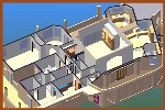 |
Image of upper level interior layout from 3D model. |
Actual interior colors not represented in this image. |
| Now look at the kitchen area in the picture above (upper right, look for the 3-bay sink). The cabinets and appliances have been modeled. This allows a view such as... |
 |
Shaded rendering of kitchen 3D model. |
Images with this level of realism quickly created from 3D model. Greater photo realism possible, at additional cost for labor. |
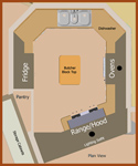 |
Plan view of kitchen layout. |
Useful for studying kitchen ergonomics. This kitchen optimized for a cook and one helper. |
| Return to the image above of the entire upper interior and notice the home office (far right middle, with a window opening onto the front portico). Below is a close-up (perspective) view of the cabinet work in that room. |
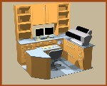 |
Shaded rendering of home admin. office custom cabinet work. |
This is a perspective view. Any view may be true perspective or isometric, from any desired viewing location or orientation. |
|
LANDSCAPING DESIGN - Utilizing 3D modeling tools and a coherent design process allows for visualization and realization not possible with traditional methods. The Casa Vista project, being a remodel, had some givens based on the features of the existing construction. There were two curb cuts in the front sidewalk which accommodated the original circular driveway. Although the driveway was eliminated I decided to use the curb cuts to provide access to two broad entry walks in the front yard which double as parking pads for the convenience of owners and guests. The large retaining walls embracing the front yard were also original to the house as purchased. These walls (which I believe were undervalued at the time of the purchase) allowed for the out-of-sight garage location and for the open north exposure of the house. Extensive use of retaining walls does allow for greater and more versatile use of the total square footage of sloping lots. Unfortunately, engineered walls (anything over three feet) are relatively expensive to construct. This requires both sellers and buyers to look for and be be aware of the value that properly designed and constructed walls can add to the property. An esthetic goal of the yard redesign was to create a high desert look. As a card-carrying lithophile (lover of rocks) I wanted to use natural rock as an accent to xeric plantings. I also wanted to use large placed native sandstone boulders to give a naturalistic appearance to the landscaping. Since large boulders would have significant visual (as well as physical) mass it was necessary to have knowledge of their size and shape during implementation of a organized design process using the same tools and techniques applied to the architectural design, as described above. Searching for suitable rocks I first contacted the local retailers. Looking at stock in the commercial yards, and inquiring as to the source and availability of sandstone, I learned that the supply primarily comes from higher elevations in Colorado. Additionally, the vendors did not stock or deliver rocks of the size I wished use. Because the available sandstone did not come from San Juan County it did not look like the local natural outcroppings. In addition the lichen crusts were very dark, typical of alpine environments in Colorado but not like that found at the lower elevations in the San Juan Basin. Lichens on sandstone in the county have a great variety of colors, from white to grey, greens, oranges and reds, browns and black. Fortunately, I was able to locate a suitable source for sandstone on property I own in the county, in an inconspicuous location where removal would not compromise future development. I took a digital camera, tape measure and notebook to the source outcrops and documented the available boulders. |
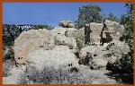 |
Source rock outcrop for large sandstone boulders used in front landscaping. |
Individual boulders given a unique identifier and measurements recorded in field notebook. |
|
The information gathered from the field survey was then used to create 3D models representing the approximate size and shape of the individual boulders which could then be located as desired when creating the model of the completed yard. |
 |
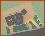
3D model of front yard. |
Models of large rocks located as intended in relation to retaining wall and decorative paving. |
|
A low front retaining wall intersecting large rocks was designed to visually suggest that rocks are native outcrops and house and walls were arranged around them. The inset section in the middle of the wall mirrors a similar inset in the rear yard retaining wall and provides a location for a yucca to be located in the sidewalk planting strip with a setback sufficient to prevent spines from overhanging the public sidewalk. |
 |
Plan view of 3D model of entire property. |
Space available for 650 sq. ft. building (workshop, studio or ?) adjacent to attached garage. |
|
Once the overall design of the front yard was completed via 3D modeling a 2D drawing was created to apply for the construction permit and to communicate the details to the contractor. |
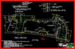 |
2D plan drawing of front yard rocks, paving, and retaining wall. |
Drawing geometry is automatically generated from the 3D model by the software. Dimensions and notes added manually. |
|
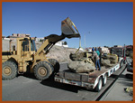
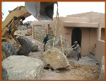
The next step was to remove the rocks from the source outcrops. A backhoe and pickup towed trailer was used for smaller rocks. A 5 cu. yd. loader, subcontracted from La Plata Construction Co., and a lowboy semi-trailer was used for the largest rocks. |
 |
Loading rocks for transport. |
Nylon slings used to minimize surface damage to rocks with lichen crust. |
 |
Unloading rocks for placement in yard. |
Largest rocks approached lift capacity of loader. |
| Having reached the construction site the larger rocks were unloaded from trailers and placed in the yard according to the plan using a measuring tape. Some of the smaller rocks were placed on an ad-hoc basis, under the supervision of the designer, where they did not directly relate to the retaining wall or paving. |
 |
Placing large rocks according to the plan. |
In some instances rocks were moved twice to make final adjustments once they had all been placed. |
| Once all of the larger rocks had been placed according to the plan, work commenced on construction of the retaining wall. |
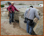 |
Constructing retaining wall formwork. |
Constant care required to minimize damage to lichen crust on rocks by reminding trades not to use them as workbenches. |
| Following casting of the retaining wall the exposed aggregate concrete flatwork was laid. Finally, the retaining wall was stuccoed to match the house. |
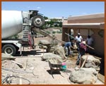 |
Pouring front yard concrete flatwork. |
Galvanized metal Key-Kold dividers. Integral color, exposed aggregate, rebar and microfiber additive reinforcement. Premium. |
| The completion of the landscaping followed installation of an automatic irrigation system with sprinkler heads. A combination of flagstone type flat rocks, river rock up to 18 inches and smaller selected sandstone rocks was used to cover the majority of the area with spaces between the rocks used as beds for xeric evergreen and deciduous plantings including numerous varieties of grasses. Please see the Projects > Casa Vista Project page for images of the completed landscaping or view the landscaping directly at 4230 N. Crescent Avenue, Farmington, NM. |
|
FINAL NOTE: The capabilities for design visualization provided by CAD tools as shown above offer an outstanding ability for both the designer and client to fully comprehend the whole design concept. Use of these tools alone, however, in no way guarantees a satisfactory outcome. The knowledge, experience and creativity of the design professional will always be the essential skills required to achieve outstanding results. Please refer to other pages on this site (e.g. Services, Projects, Design Process and Visual Gallery) to gain a fuller understanding of what architectural knowledge, experience and creativity Synoptic Designs can offer potential clients. |
|
Definition: (syn-op' tic Seeing the whole together)
|
|
Available Design Related Software CoCreate OneSpace Designer, including Freeform, Annotation (automatically generates 2D drawings from the 3D models), and Photo Realistic Imaging Modules. Can import 3D data in IGES, I-Deas, Inventor (AutoDesk), PRO/E, Unigraphics, SolidEdge, SolidWorks formats. Can export 3D data in IGES, ACIS, STL, VRML, CATIA, I-Deas, Inventor, PRO/E, Unigraphics, SolidEdge, and SolidWorks formats. Can import and export 2D data in IGES, VRML, DXF, DWG, DWF, SVG formats; CoCreate OneSpace Drafting (somewhat redundant with Annotation package above but useful for creating 2D line drawings and graphics that are not derived from 3D solid models); Adobe Photoshop CS2; The Panorama Factory (creates panoramic images by stitching together successive overlapping individual pictures); TextBridge OCR software; DeLorme Topo USA; DeLorme Street Atlas USA; USAPhotoMaps; Google Earth; OpenOffice Suite (documents, spread sheets and presentation); Broadband Internet (Satellite) Available Design Related Hardware Dell Precision Workstation 530, 1.8 GHz P4, 1 Gb RAM, 3D Labs Wildcat III 6110 graphics card (dual DVI outputs), dual hard drives, DVD/CD +/-R/RW drive, CD +/- R/RW drive, optical mouse, keyboard, Wacom graphics tablet, dual 18 LCD monitors (2560 X 1024 effective desktop area); Epson Perfection 3200 Photo Scanner; Epson Stylus Photo R320 Printer; Epson Stylus Pro 7500 Printer 24 wide X available media length, sheet or roll media, including sheet stock up to 1/8 thick (foamboard). Prints on plain paper, watercolor paper, canvas, glossy photo paper, etc. Archival quality pigment based ink (est. 75 year life); Nikon D50 SLR digital camera; Nikon 18-55mm zoom lens; Canon F-1 35 mm SLR Camera, assorted lenses; Soligor 8X20-50 Zoom Binoculars; CST/Berger LaserMark Laser Level and accessories (+/- 1/4 per 100'); Wheel measuring device, 9999 feet; 100' Tape Measure.
|
| Contact
Synoptic Designs |